Physical installation and mounting
Overview
This guide covers the complete physical installation of the SenArch ARCH-1 Standard LoRaWAN Gateway — from preparing the enclosure to mounting the hardware and powering up the system.
Prerequisites
Required tools (not included, all sizes metric):
- M6 Allen key
- Phillips screwdriver
- At least one of: a ratchet wrench set, combination wrenches in sizes 10, 13, and 17, or an adjustable wrench
For tripod mounting (optional accessory) — also:
- M8 Allen key (umbraco)
- M6 wrench or socket (to assemble the tripod) and M8 wrench or socket (to fasten the feet)
- Power drill with a masonry bit (for the M8 holes)
- Hammer — to seat the expansion bolts
- Three heavy pavement tiles (40 × 40 × 8 cm recommended)
- Three M8 expansion bolts, each with a nut and washer
Power components — these must meet the following requirements, or the system may fail:
| Component | Requirement |
|---|---|
| Battery | AGM, 12 V, 50 Ah or 100 Ah |
| Solar panel | Poly/mono-crystalline, 50 W, 100 W, or 150 W. 18 V is ideal; 12 V also works |
| Battery fuse | ATO, 32 V, 10 A |
| PCB fuse | ATO, 32 V, 10 A |
| Gateway fuse | ATO, 32 V, 3 A |
To replace a blown fuse, see The gateway has no power.
Before you start
- Do not install the product if you cannot safely lift and carry more than 20 kg.
- Keep the device away from open flames and within its operating temperature range.
- Never use power cables that are damaged.
Seat the CoHost backup battery
Do this first, before mounting anything.
Depending on how your gateway shipped, SenArch may have already seated the battery for you. In most cases, though, it ships strapped above the holder and you need to move it into place:
- Place the gateway enclosure on a flat, stable table.
- Open the enclosure with a Phillips screwdriver.
- Locate the CoHost backup battery inside. If it is already seated in the battery holder, no action is needed.
- If the battery is held above the holder by a velcro strap, unfasten the strap.
- Before installing the battery, find the + and − markings on the PCB next to the battery holder.
- Seat the battery into the holder so its terminals match the + and − markings.
- Fasten the velcro strap back over the battery to hold it in place.
This connects the CoHost backup battery so the CoHost can monitor the gateway. If the gateway uses LTE, leave the enclosure open and install the SIM card next; otherwise close it.
Install the SIM card
Only needed if the gateway uses cellular (LTE) backhaul. Do this while the enclosure is still open.
- Locate the SIM card holder on the backplane, between the concentrator and the modem.
- Push the SIM card slot shield upwards to unlock and open it.
- Insert (or replace) the micro-SIM (3FF) — gold contacts facing down, with the chamfered corner aligned to the holder key.
- Close the shield and push it downwards until it clicks to lock it.
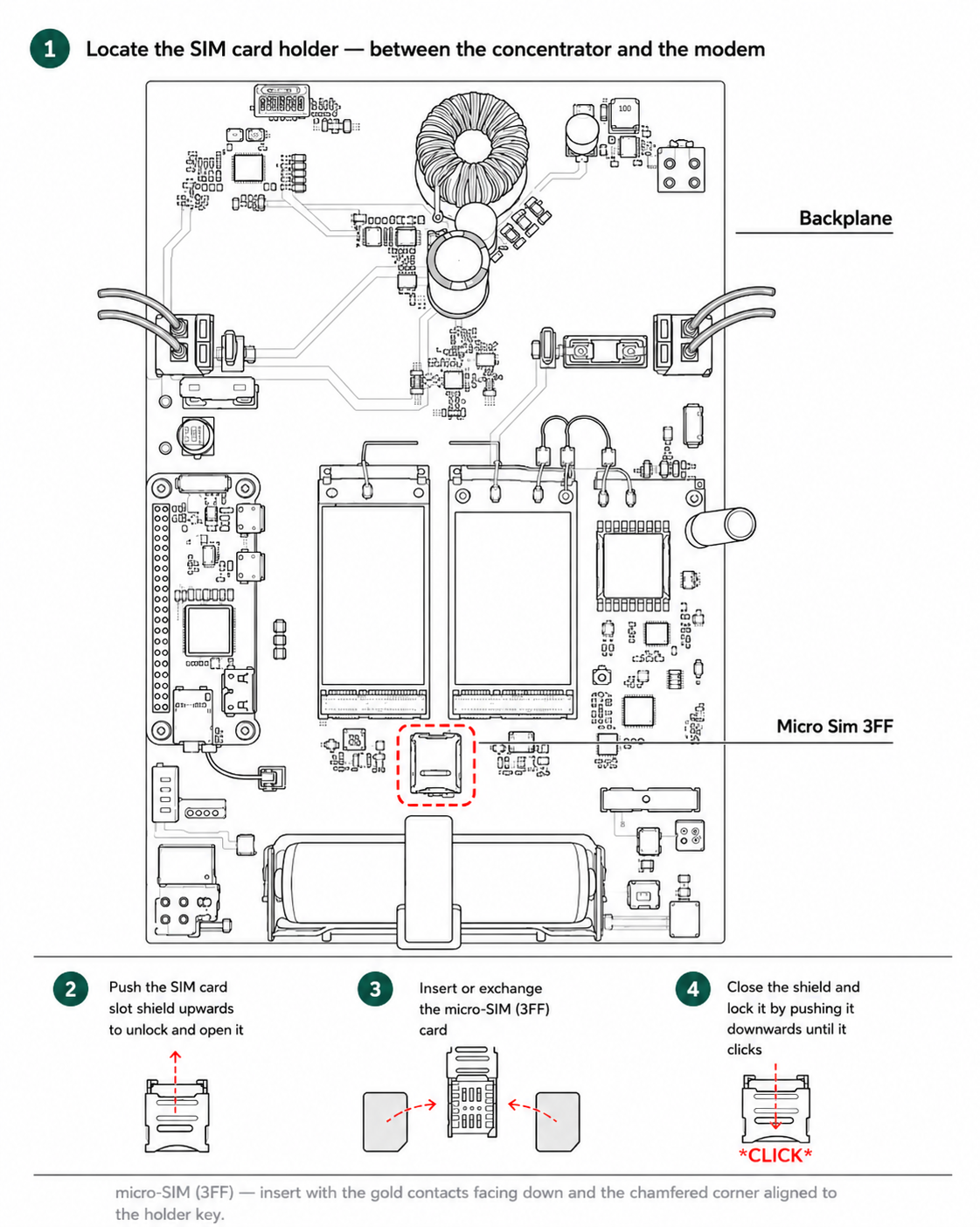
Close the enclosure when you are done.
Mounting options
Choose your mounting method:
- Pole mounting (standard, recommended)
- Tripod mounting (optional accessory)
- Wall mounting (optional, requires expansion bolts)
The steps below describe pole mounting. A 48 × 2000 mm pole (galvanized steel or aluminium, 3 mm wall thickness) is required and not included. See Alternative mounting methods for tripod and wall mounting.
Solar panel placement
Before mounting, plan the solar panel position:
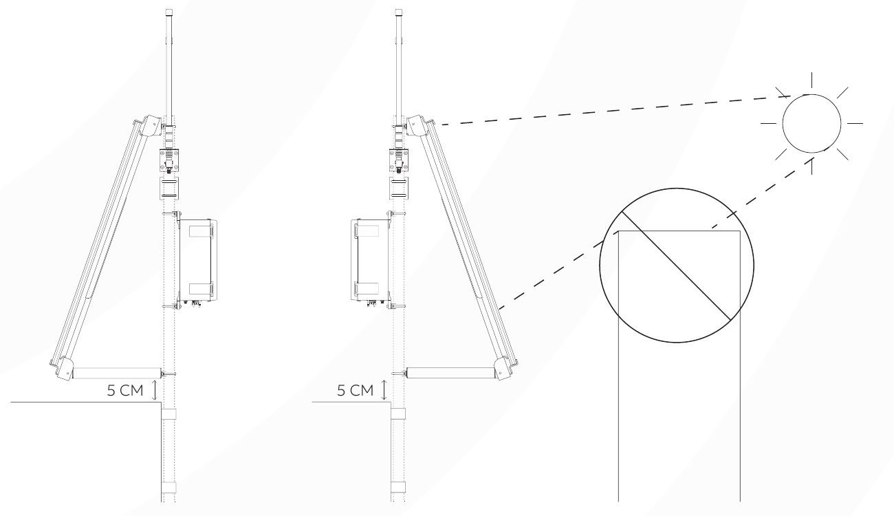
- Keep at least 5 cm of clearance below the solar panel frame, clear of any obstacle.
- Choose a spot where the panel is unobstructed by shade for as many hours a day as possible.
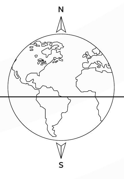
- Point the panel south in the Northern Hemisphere, or north in the Southern Hemisphere.
Battery cabinet installation
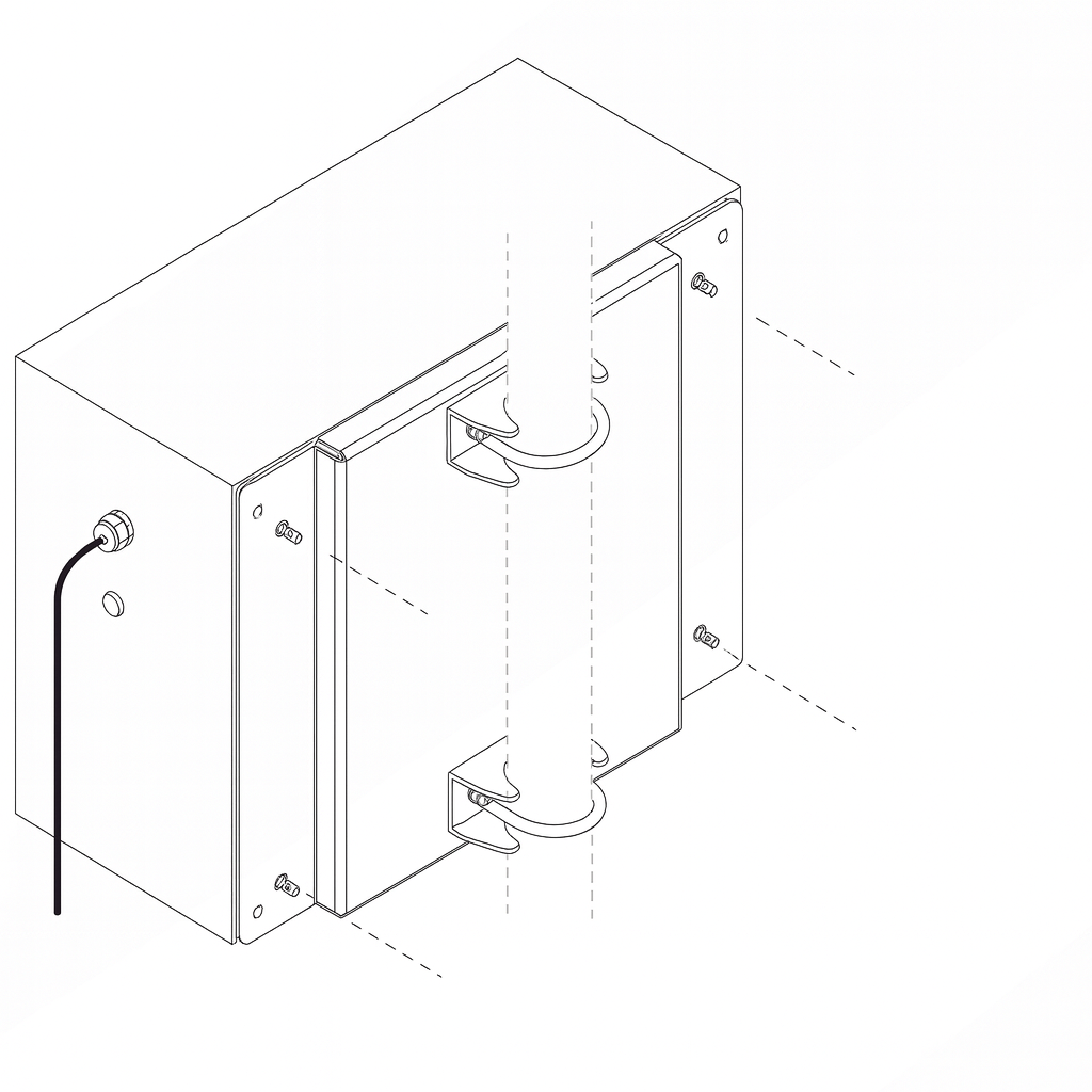
- Attach the battery-enclosure mounting plate to the pole with the U-bolts, U-bolt brackets, and M8 self-locking nuts.
- Position the battery cabinet against the mounting plate so the holes line up.
- Fasten the cabinet to the plate with the supplied M6 and M8 round-head bolts and self-locking nuts.
- Place the battery slider in the bottom of the cabinet.
The cabinet must remain stable when pushed sideways.
Solar panel installation
- Fasten the bottom of the solar panel frame arm to the pole with a U-bolt, U-bolt bracket, and two M8 self-locking nuts. Fasten tightly.
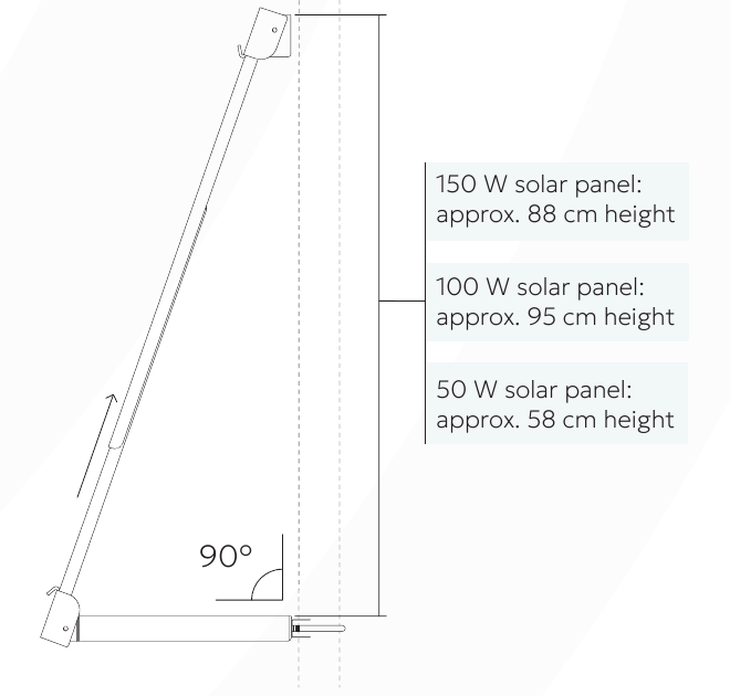
- Extend the frame arm to suit your panel, keeping the bottom plate at a 90° angle to the pole. Approximate heights: 50 W ≈ 58 cm, 100 W ≈ 95 cm, 150 W ≈ 88 cm.
- Fasten the top of the frame to the pole the same way.
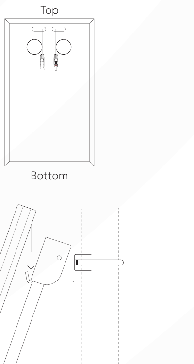
- Hang the panel on the hook ledge with the wired end at the top, centred on the pole.
- Loosen the bottom U-bolt, extend the frame down until the hook ledge locks the bottom edge of the panel, then retighten.
- Confirm the panel cannot move vertically.
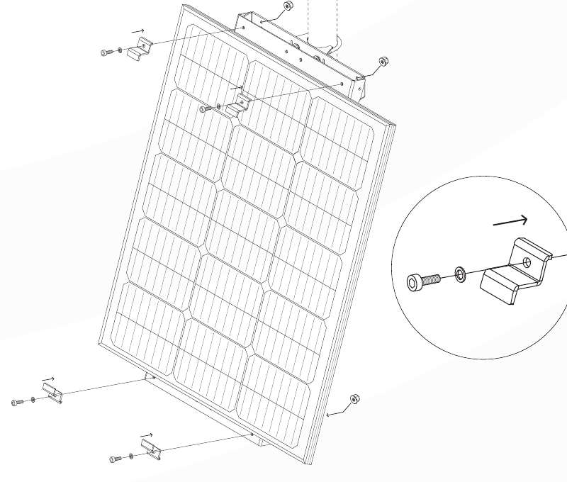
- Secure the panel to the frame with the mounting brackets, socket-head cap screws, washers, and self-locking nuts, then tighten all frame screws.
Solar panel cables must point downwards to prevent water ingress.
Antenna installation
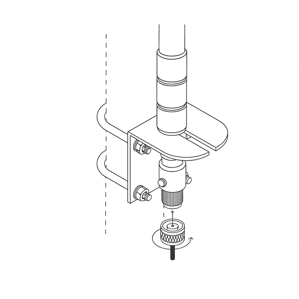
- Unscrew and set aside the bolt and washer from the base of each antenna.
- Place the antenna base into the hole in the mounting bracket and refasten it with the bolt and washer from step 1.
- Fix the bracket to the pole using the U-bolts, washers, lock-washers, and bolts.
- Tightly screw the lightning arrester onto the base of the antenna.
- Tightly screw the N-type coaxial cable onto the bottom of the lightning arrester.
- Wrap the arrester in vulcanizing tape for weather protection (tape not included).
Antennas must be vertical and must not touch metal structures.
Grounding
For safety, connect the grounding wire: the M4 end to the lightning arrester on the antennas, and the M6 end to a metal surface such as the mounting pole.
Gateway enclosure installation
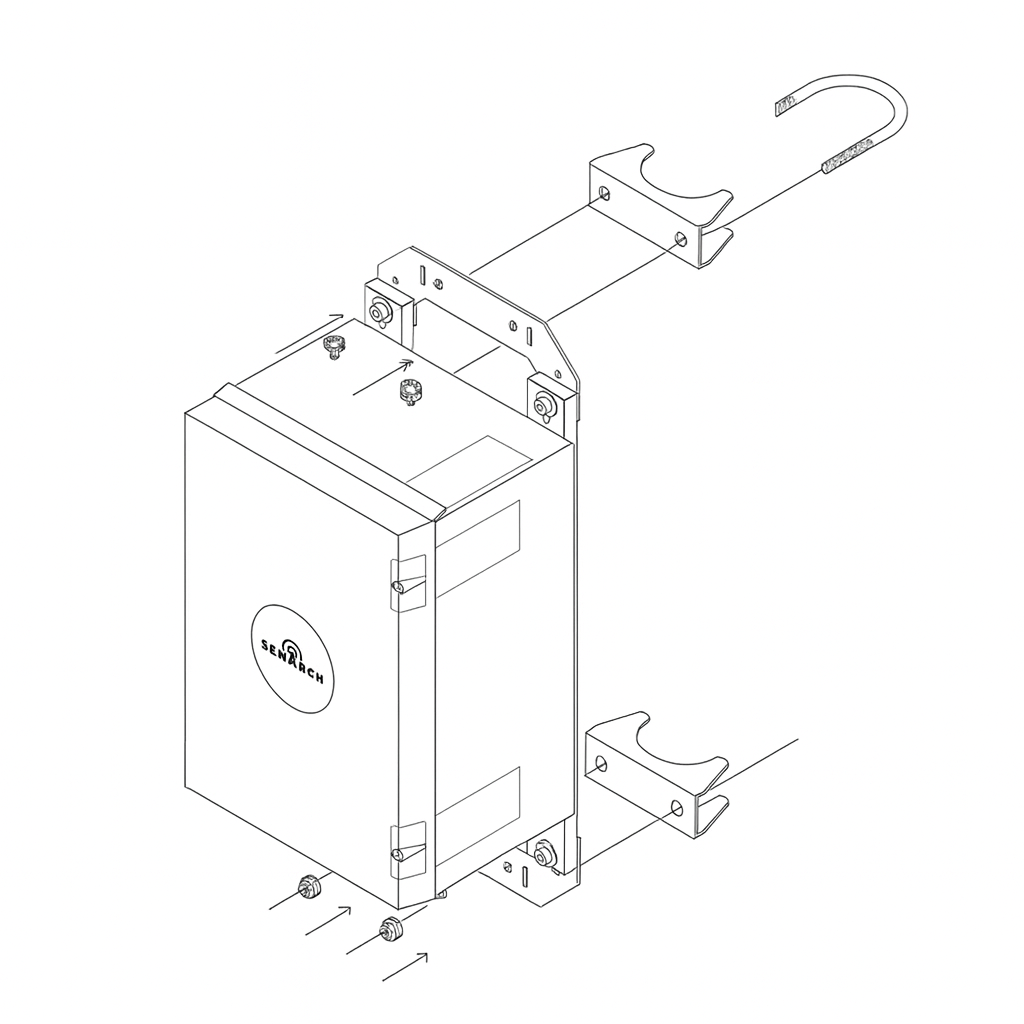
- Screw the mounting brackets onto the enclosure with the socket-head cap screws, washers, and self-locking nuts. It is easiest to do this straight out of the box.
- Attach the brackets to the pole with the U-bolts, U-bolt brackets, and M8 self-locking nuts.
- Mount the enclosure behind the solar panel so it is shaded from direct sunlight.
The enclosure must sit upright without tilt or wobble.
Cable connections
Connect the cables to the ports on the bottom of the gateway enclosure (labelled LoRA Antenna, LTE Antenna, Solar Positive, Solar Negative, and Battery Power) in this order:
- LoRa antenna cable
- LTE antenna cable
- Solar panel cable (positive and negative)
Do not connect the battery power yet.
Weatherproof the connectors
For a permanent installation, wrapping the N-type coaxial connectors in vulcanizing tape is recommended — it seals the outdoor RF connections against moisture. SenArch does not supply the tape; wrapping the connectors is up to you.
Powering up the system
- Tilt the battery with its terminals towards you, without touching the terminals.
- Lift the battery into the cabinet, resting the bottom corner just inside, then let it settle upright against the battery slider.
- Pull each eye connector through a terminal insulating cap, then connect them to the battery — red to the positive (+) terminal and black to the negative (−) terminal. Pull the caps over the terminals so each is fully covered.
- Make a downward loop in the battery cable and secure it with a tie-wrap, so rainwater drips away from the enclosure port instead of running into it.
- Plug the battery cable into the Battery Power port on the gateway enclosure.
The system powers up automatically.
Check polarity
Never reverse the battery polarity. Connect red to the positive (+, red) terminal and black to the negative (−, black) terminal — incorrect wiring may damage the system.
Alternative mounting methods
Mounting with metal bands
Instead of U-bolts, you can fasten the gateway enclosure, solar panel frame, and battery enclosure to the pole with metal bands. Use a high-strength, durable band no wider than 19 mm (SenArch recommends Band-It bands; bands not included). Tighten the band according to its own instructions.
Tripod mounting
The SenArch tripod is an optional accessory. Install the components in the same order as pole mounting: battery enclosure → solar panel → antennas → gateway enclosure. See Prerequisites for the tripod tools and materials. Then secure the tripod to the ground so it cannot tip over.
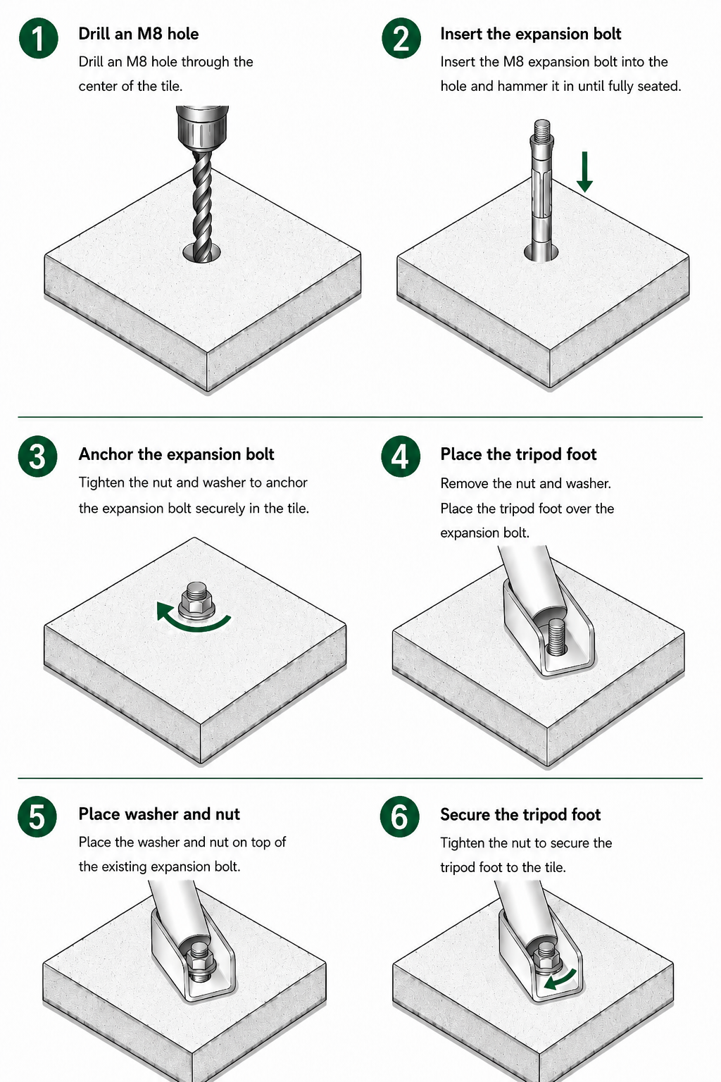
On a hard surface — bolt each foot to a tile. Use one heavy pavement tile for each tripod foot. Repeat the installation for all three tripod feet (3 tiles in total).
Tile size
Recommended tile size: 40 × 40 × 8 cm (50 × 50 × 8 cm is also acceptable). The tile thickness must be at least 8 cm.
- Drill an M8 hole through the centre of the tile.
- Insert an M8 expansion bolt into the hole and hammer it in until fully seated.
- Tighten the nut and washer to anchor the expansion bolt in the tile.
- Remove the nut and washer, then place the tripod foot over the expansion bolt.
- Place the washer and nut back on, on top of the expansion bolt.
- Tighten the nut to secure the tripod foot to the tile.
Wall mounting
Wall mounting is an example, not a step-by-step procedure — the right method depends on your wall. Research the correct fixings for your wall type first. As a guide:
- Use M8 carbon-steel expansion bolts (M6 for antennas) with M8 self-locking nuts (not included).
- Measure the bolt spacing for each module before drilling.
- Install the solar panel on its frame before mounting the frame to the wall.
- For limited space, mount a short pole (≤ 48 mm wide) on the wall and attach the antennas with U-bolts.
Depending on how far apart the modules are mounted, extension cables may be needed.
Next steps
- Connect to the gateway to begin configuration in the Gateway UI
- Confirm all connections and monitor gateway health through your LoRaWAN network server and the CoHost